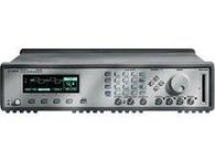

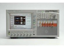
The Agilent / HP 81141A Serial Pulse Data Generator enables reliable physical layer measurements for high-speed bus designs and for scientists conducting fundamental lab research. The Agilent / HP 81141A Serial Pulse Data Generator provides what is needed to conduct physical layer tests e.g. precision low jitter signals or full control of data streams for stress tests. Its linear delay modulation is essential for jitter tolerance and jitter transfer measurements.
Features and Specifications of:
Features:
●Pulse, Data Pattern and PRBS generation up to 7 GHz
●Differential outputs for data, clock and trigger
●Trigger and external clock input
●Fastest transition times < 20 ps
●Data formats: NRZ, R1 and RZ
●Low jitter, high accuracy signals with Jitter < 1 ps RMS
●1 GHz jitter modulation bandwidth
●PRBS generation from 25 -1 to 231 -1
●32 Mbit Memory for long, "real world" patterns
●Sequencing and looping for protocol based data
●Event trigger capabilities
●Subrate clock for easy generation of reference clock
Specifications:
●Frequency: 150 MHz to 7 GHz
●Output channels:
oSingle channel data and clock
oDifferential or single ended
●Triggering:
oAux In (Trigger In): Lets user connect a signal to switch between Pattern A and B, or to suppress the output signal
oTrigger Out: Lets user provide a trigger for another device
●Data formats: RZ, R1, NRZ
●Duty cycle: 70ps to period -70ps
●Clock/data delay range: ±0.75 ns with a 100 fs resolution
●Delay modulation range: -100 ps to 100 ps
●Transition times (10 / 90): < 25 ps
●Jitter (clock mode): 1 ps rms typical
●Jitter (data mode): 9 ps pp typical
●Jitter modulation bandwidth: DC - 1 GHz
●Data output amplitude / resolution: 0.1V to 1.8V with 5mV resolution
●Output voltage window: -2V to 3V
●Sequencing and looping: 1 level of up to 4 blocks
●Memory: 32Mbit
●Channel output connector: 2.4 mm
●Interfaces: GPIB, LAN, parallel printer, VGA, 4 x USB 2.0, 1 x USB 1.1
●Data Output (DATA OUT)
oRange of operation:
■150 MHz to 7 GHz
■For RZ/R1: min. 620 MHz
■(< 620 MHz only with external clock)
■For RZ/R1/pulse up to 7 GHz
oFrequency accuracy: ± 15 ppm typical
oWidth accuracy: ± 20 ps
oFormat: NRZ, normal or inverted, RZ, R1
oAmplitude/resolution: 0.10 V to 1.8 V, 5 mV step
oOutput voltage window: -2.0 V to +3.0 V
oPredefined levels: ECL, PECL (3.3 V), LVDS, CML
oTransition times:
■(20% to 80%) < 20 ps
■(10% to 90%) < 25 ps
oLow intrinsic jitter: 9 pspp typical
oClock/data delay range: ±0.75 ns in 100 fs steps
oExternal termination voltage: -2.0 V to +3.0 V
oCrossing point: Adjustable from 20% to 80% typical
oRZ/R1 width: 70 ps to period -70 ps
oSingle error inject: Adds single errors on demand
oFixed error inject: Fixed error ratios of 1 error in 10n bits, n = 1...12
oInterface: Differential or single-ended, DC coupled, 50 Ω
oConnector: 2.4 mm female
●Clock Output (CLK OUT)
oAmplitude/resolution: 0.1 Vpp to 1.8 Vpp, 5 mV steps
oOutput voltage window: -2.00 V to +2.8 V
oTransition times:
■(20% to 80%) < 20 ps
■(10% to 90%) < 25 ps
oExternal termination voltage: -2.0 V to +3.0 V
oJitter: < 1 psrms typical
oInterface: Differential or single-ended, DC coupled, 50 Ω output impedance
oConnector: 2.4 mm female
●Subrate Clock Output (SUB CLK OUT)
oUsed to generate reference clocks that are subrates of the data rate
oDivider factors: N = 2,3 ... 128
oLevels:
■High: + 0.5 V
■Low: - 0.5 V typical
oTransition times: 35 ps typical
oInterface: DC coupled, 50 Ω
oConnector: SMA female
●Clock Input (CLK IN)
oUses an external clock as a generator clock
oAmplitude: 200 mV to 2 V
oInterface: AC coupled, 50 Ω nominal
oConnector: SMA female, front panel
●10 MHz Reference Input (10 MHZ REF IN)
oIf a 10 MHz reference clock is applied, the PLL generating the internal clock for the generator clock will lock to the applied signal
oAmplitude: 200 mV to 2 V
oInterface: AC coupled, 50 Ω nominal
oConnector: BNC, rear panel
●10 MHz Reference Output (10 MHZ REF OUT)
oUses an external clock as a generator clock
oAmplitude: 1 V into 50 Ω typical
oInterface: AC coupled, 50 Ω output impedance
oConnector: BNC, rear panel
●Delay Control Input (DELAY CTRL IN)
oExternal signal applied to Delay Control Input varies the delay between Data Output and Clock Output
oThis can be used to generate jittered signals to stress the device under test
oRange: -100 ps to +100 ps
oSensitivity: 400 ps/V typical
oLinearity: ±5% typical
o3dB modulation bandwidth: DC to 1 GHz
oLevels: -250 mV to +250 mV
oInterface: DC coupled, 50 Ω nominal
oConnector: SMA female
●Error Add Input (ERROR ADD)
oAdds a single error to the data output for each rising edge at the input
oLevels: TTL compatible
oInterface: DC coupled, 50 Ω nominal
oConnector: SMA female
●Trigger Output (TRIGGER OUT)
oProvides a trigger signal synchronized with the pattern
oFor use with an oscilloscope or other test equipment
oPulse width: Square wave
oTransition times: 35 ps typical
oLevels:
■High: +0.5 V
■Low: -0.5 V typical
oInterface: DC coupled, 50 Ω nominal, single ended or differential
oConnector: SMA female
●AUX Input (AUX IN)(Trigger In)
oWhen the Alternative Pattern Mode is activated the memory will be split into tow parts
oUser can define a pattern for each part
oLevels: TTL compatible
oInterface: DC coupled, 50 Ω nominal
oConnector: SMA female
Hot Tags: used pulse data generator agilent 81141a, China, manufacturers, Suppliers, Factory, buy, low price, in stock, Used Function Generator Tektronix AFG3251, Used Differential Output Module Tektronix DTGM32, Used Pulse Data Generator Agilent 81141A, Used Function Generator Tektronix AFG3252C, Used Pulse Pattern Generator Agilent 8110A, Used Pulse Data Generator Agilent 8114A